computational tectonics
Academic research
Harvard GSD, 2010
waterjet-cut steel plate
waterjet-cut aluminum sheet
MathCAD
Rhino3d
MasterCAM
(Scroll down for image gallery)
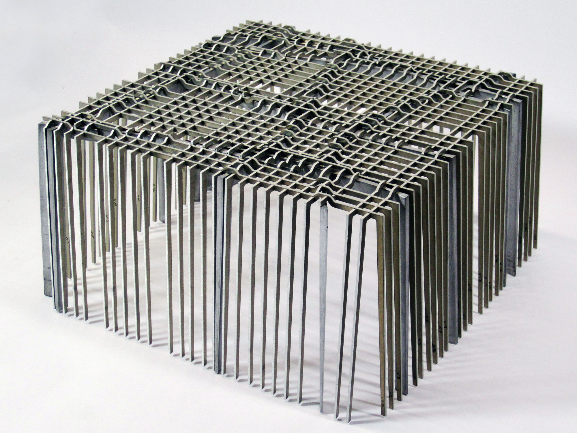
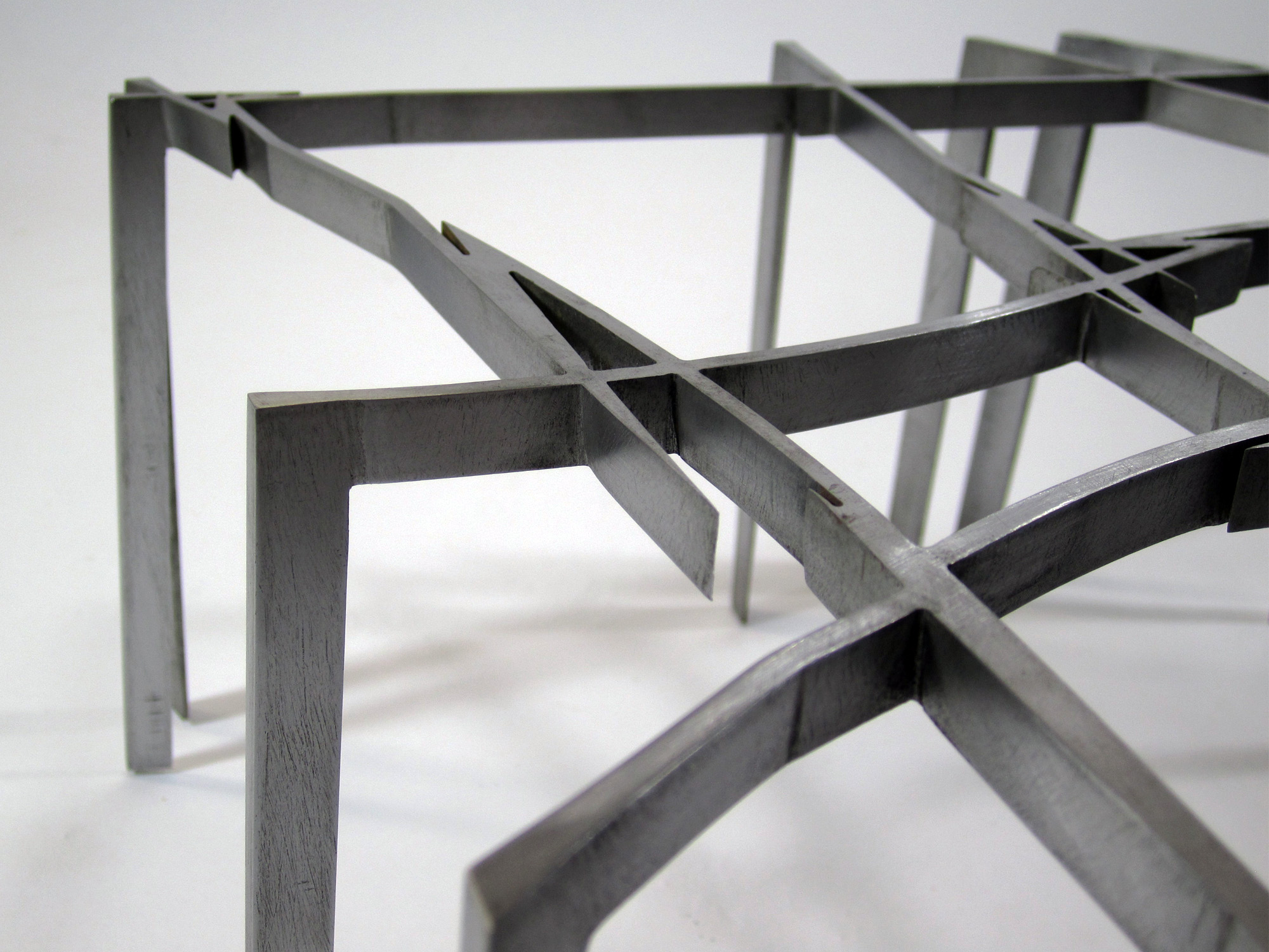
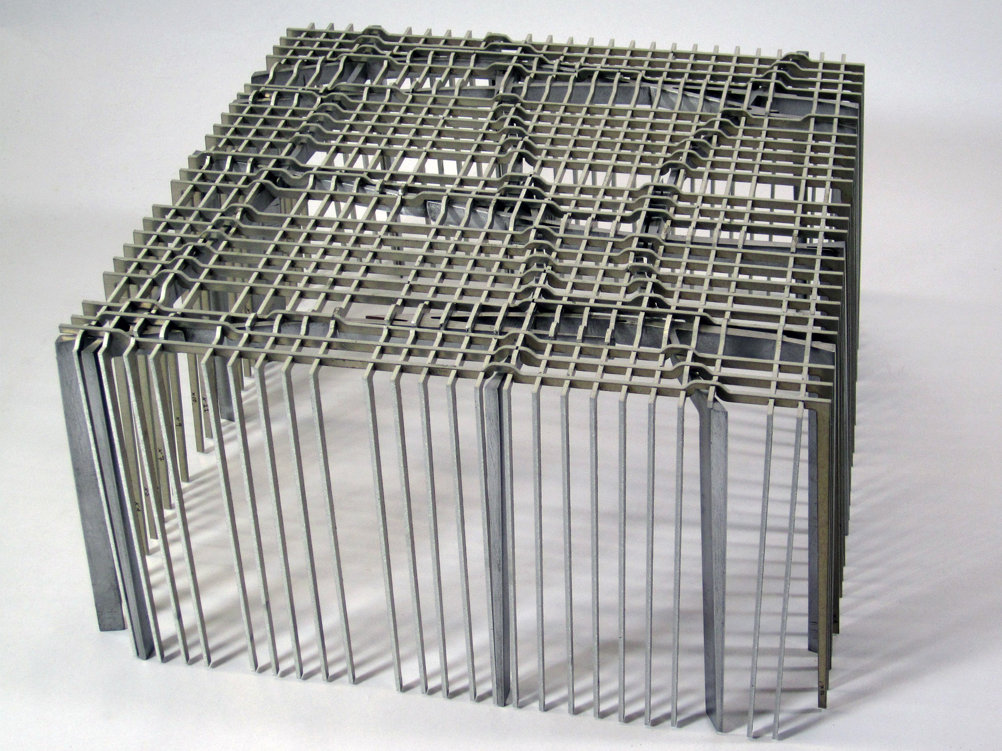
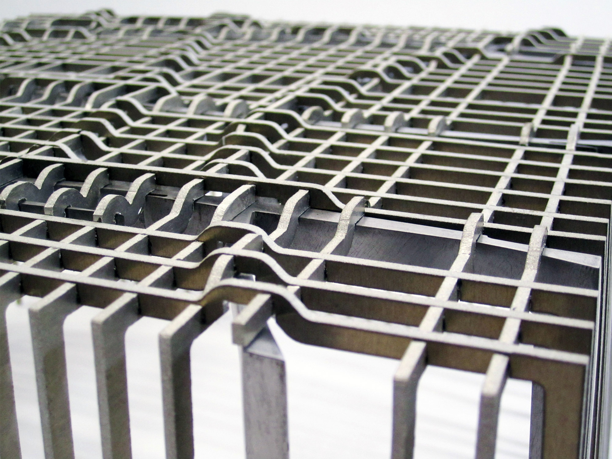
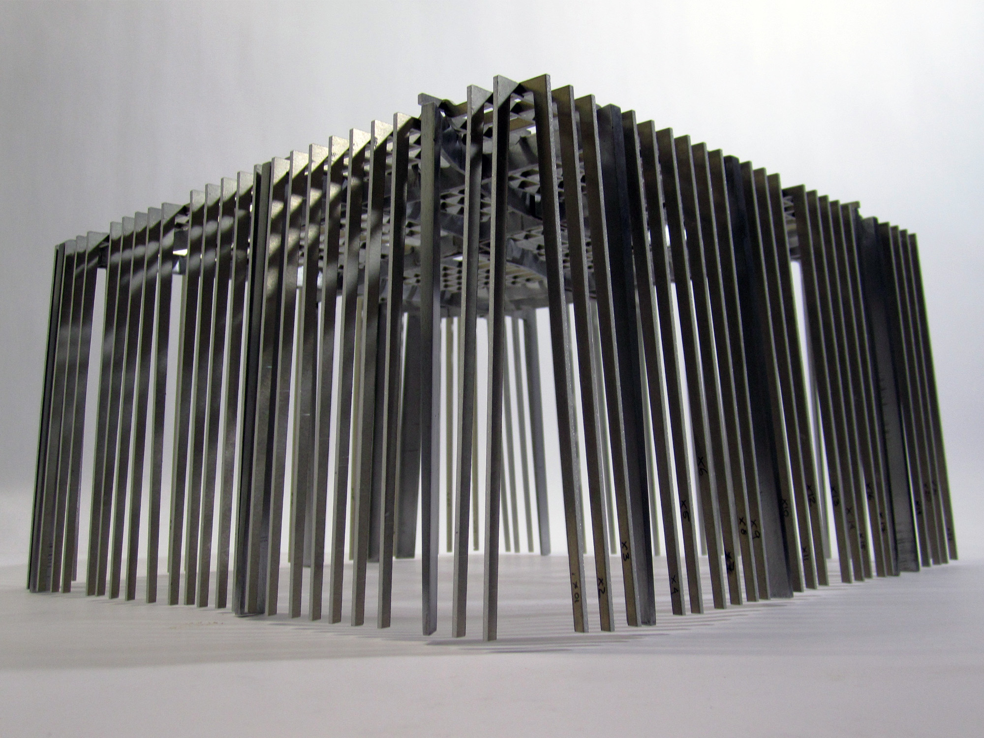
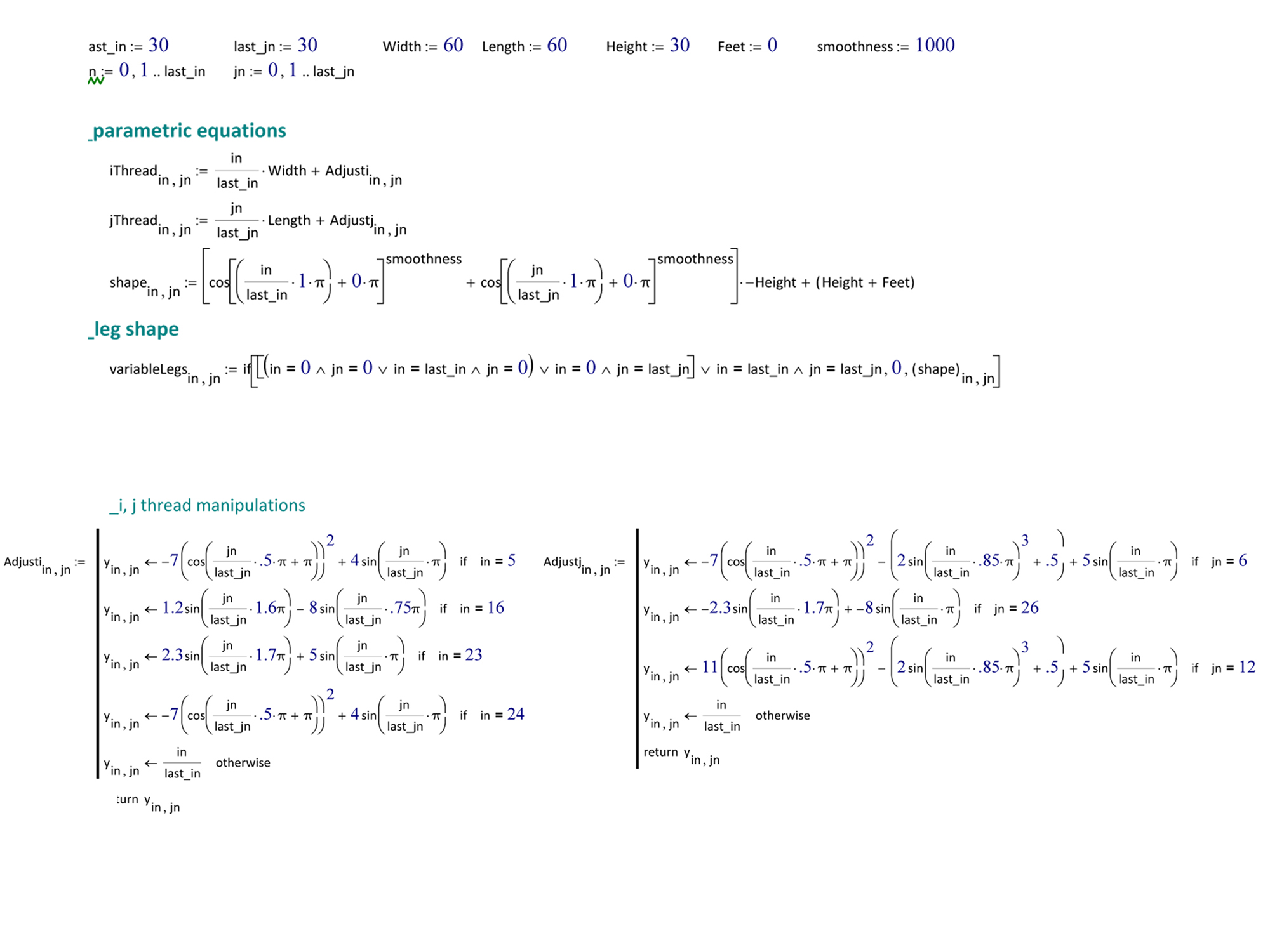
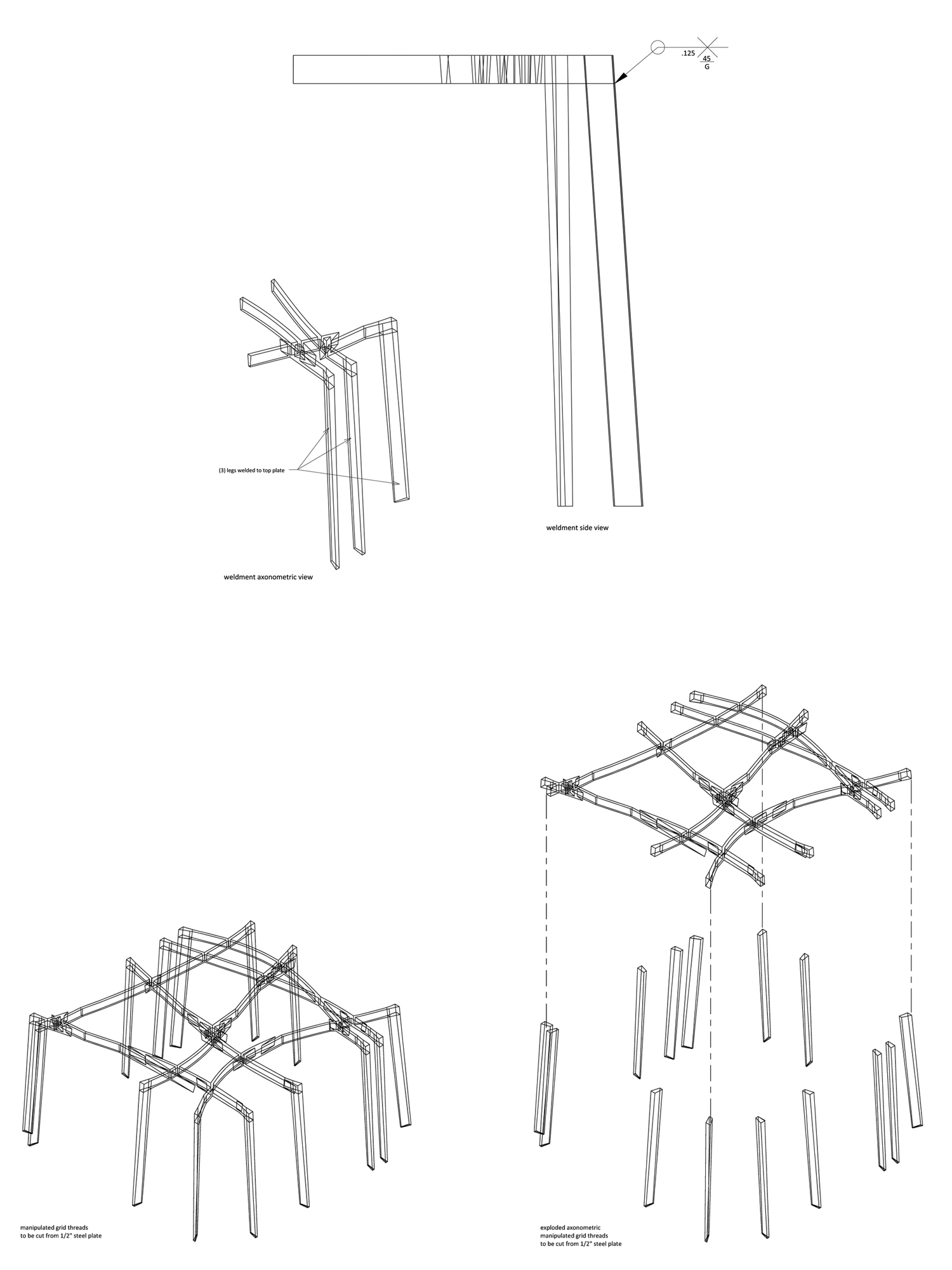
Constructed of steel and aluminum, this project investigated the translation of a purely computational design method into a physical tectonic object. Working within a software environment that is intended for solving technical calculations, the design process was based on the graphing of a three-dimensional equation.
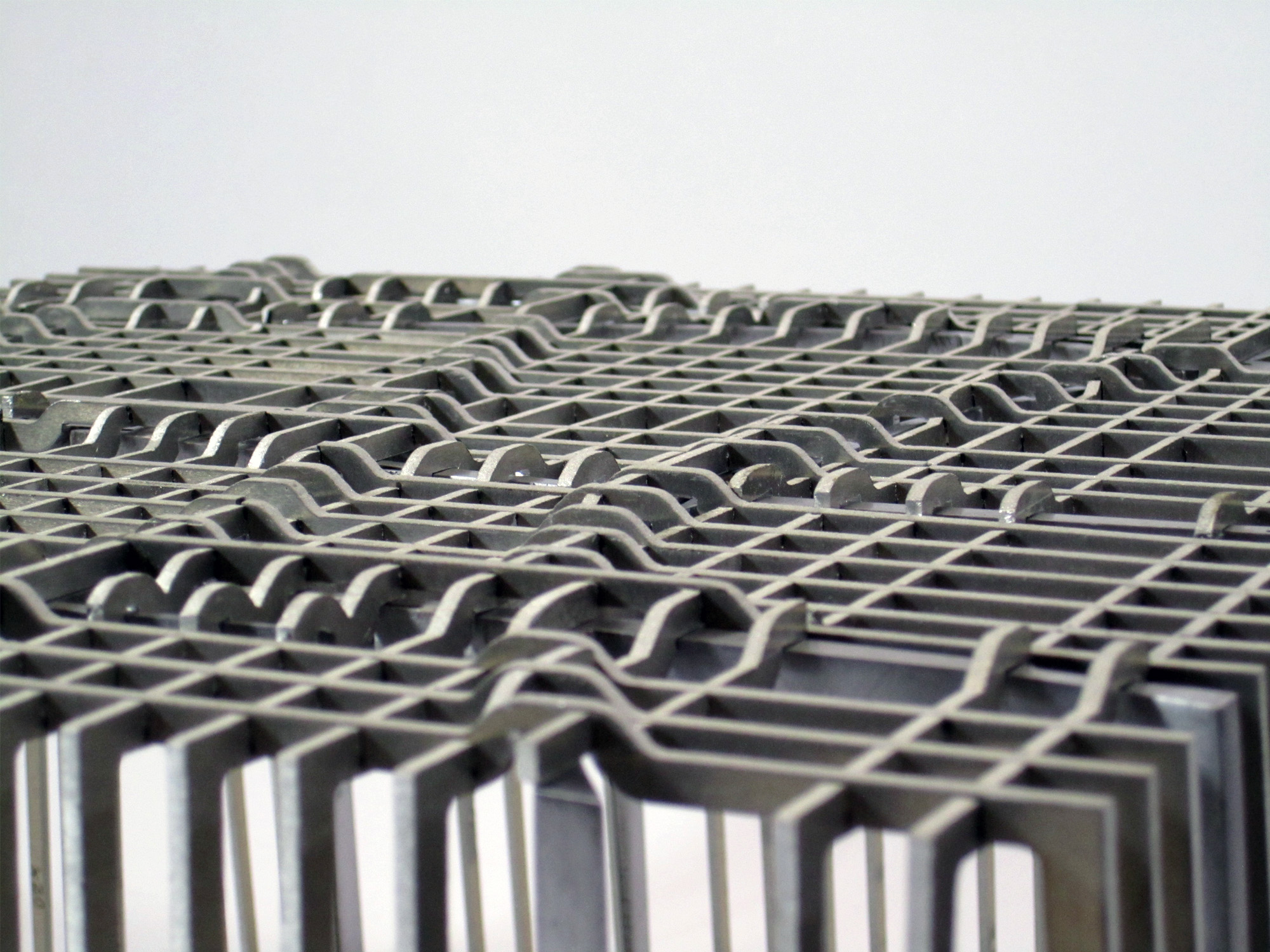
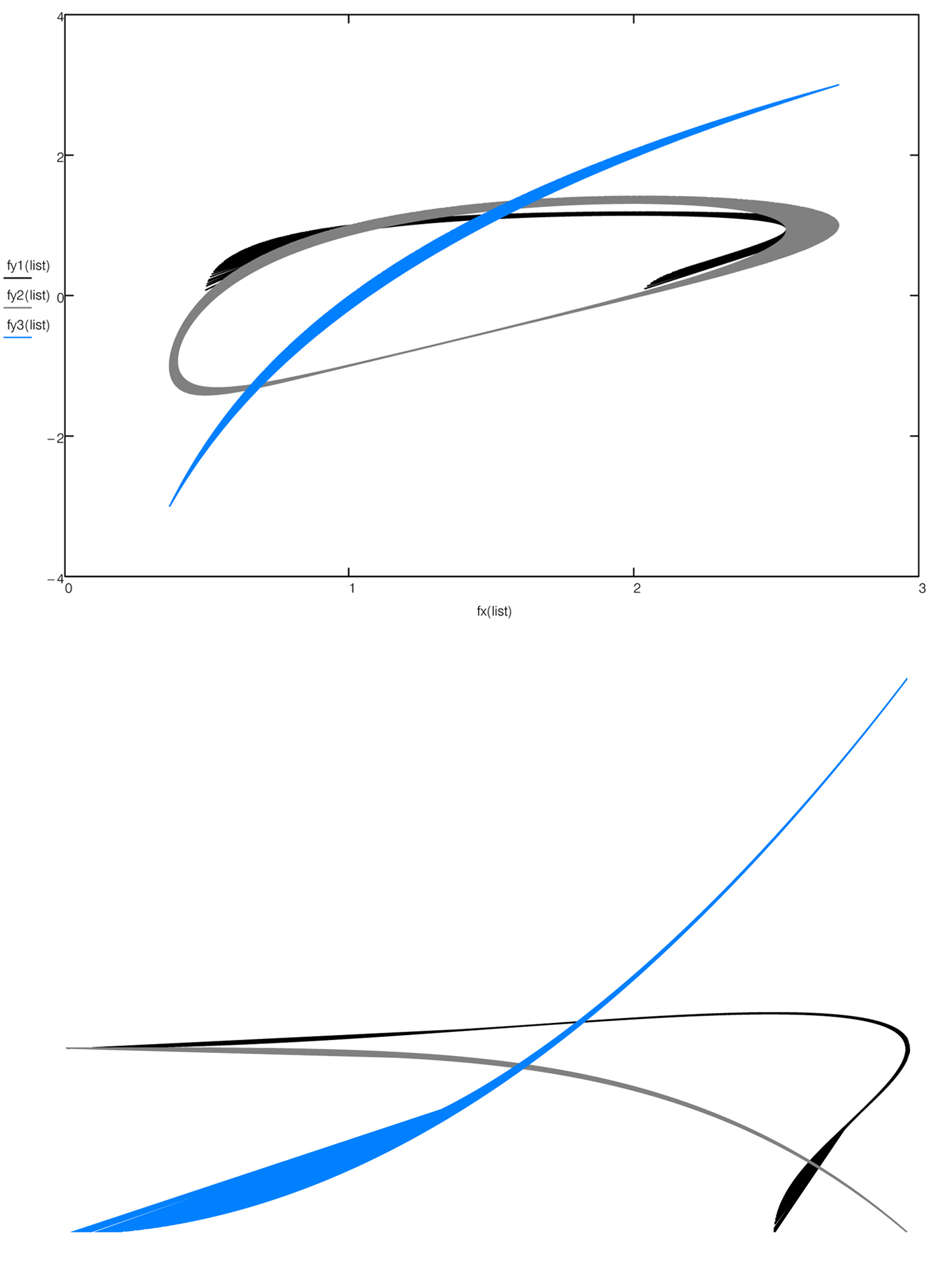
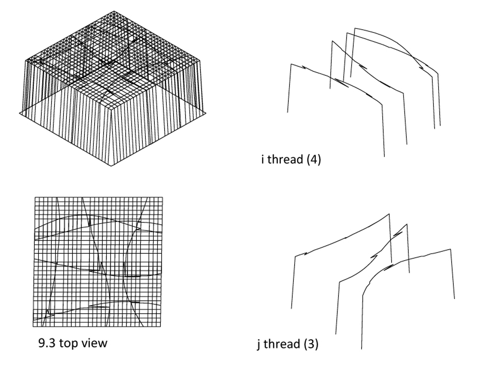
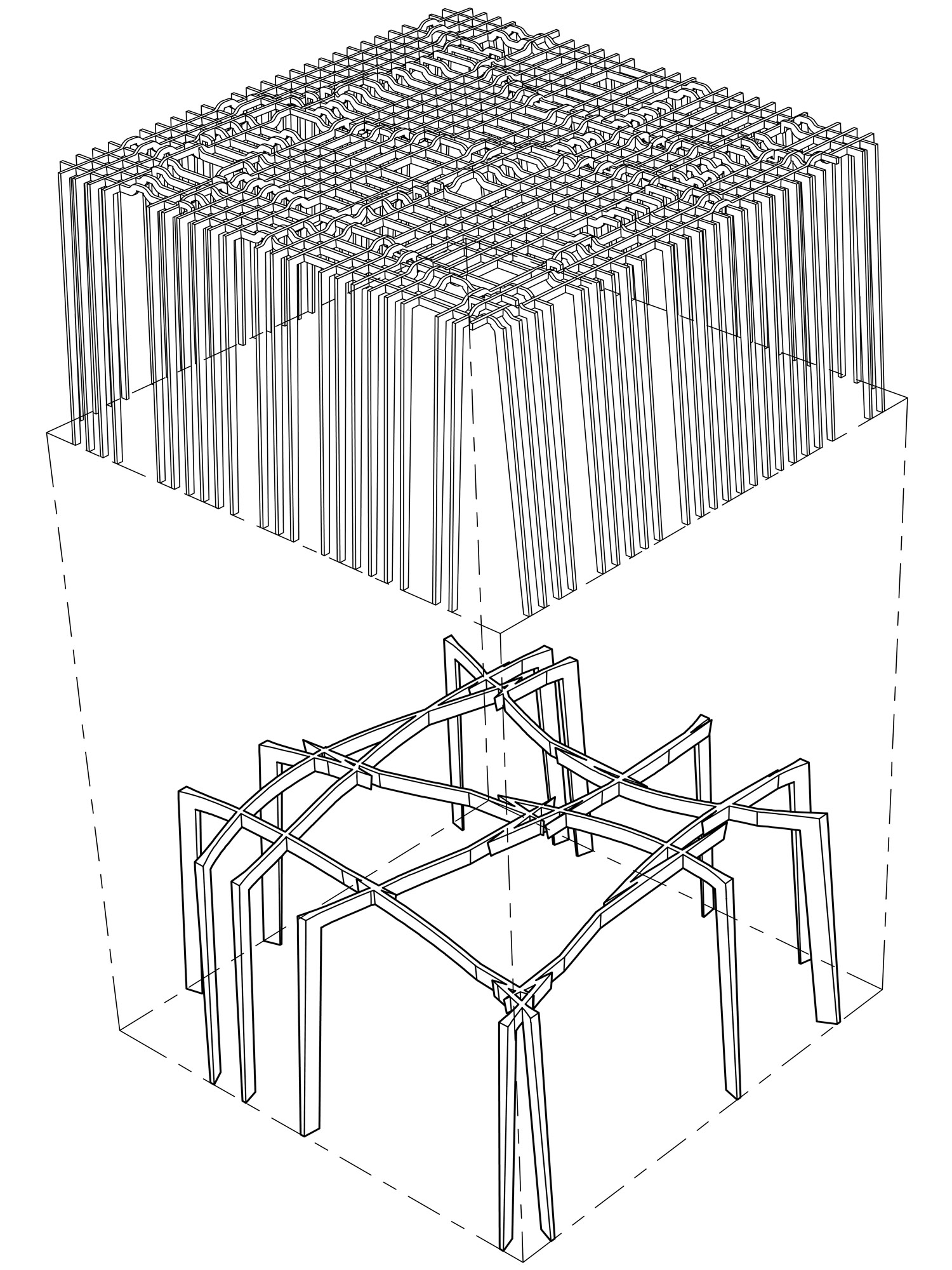
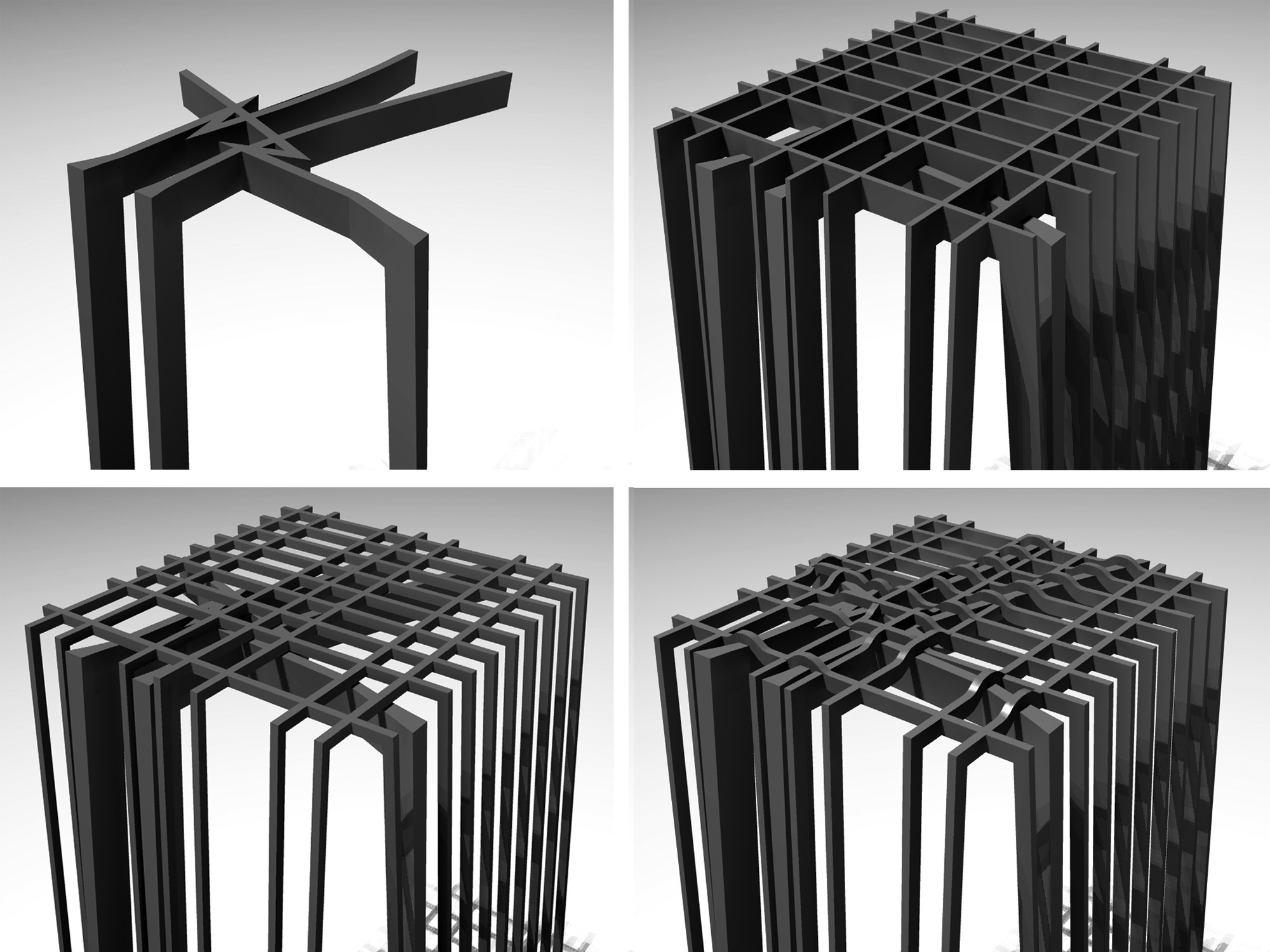
The mathematical phase of this project began with a known equation that graphs Cartesian X-Y “threads” into a box-like form. Additional lines of code were added to the equation, which manipulated these threads through the programming logic of a series of conditional “if-then” statements. This allowed for a precision in choosing which parts of the equation were modified and controlled. However, the ways in which the individual manipulations would interact was unpredictable. Limited control was gained through a heuristic series of design iterations that brought an intuitive feel.
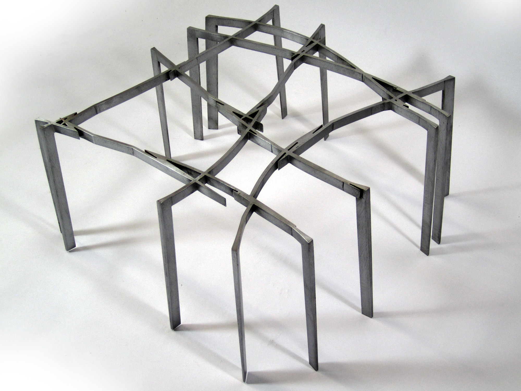
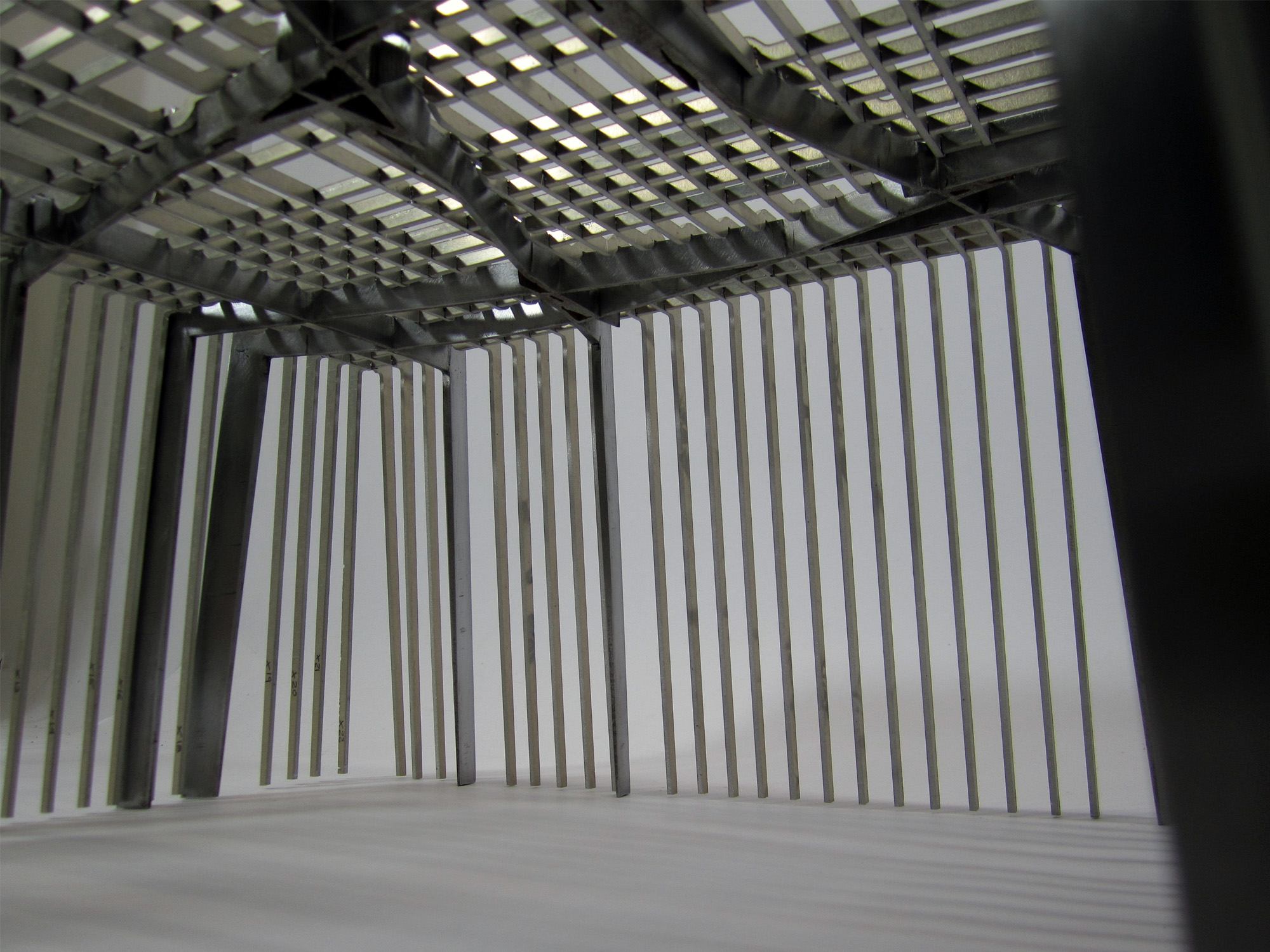
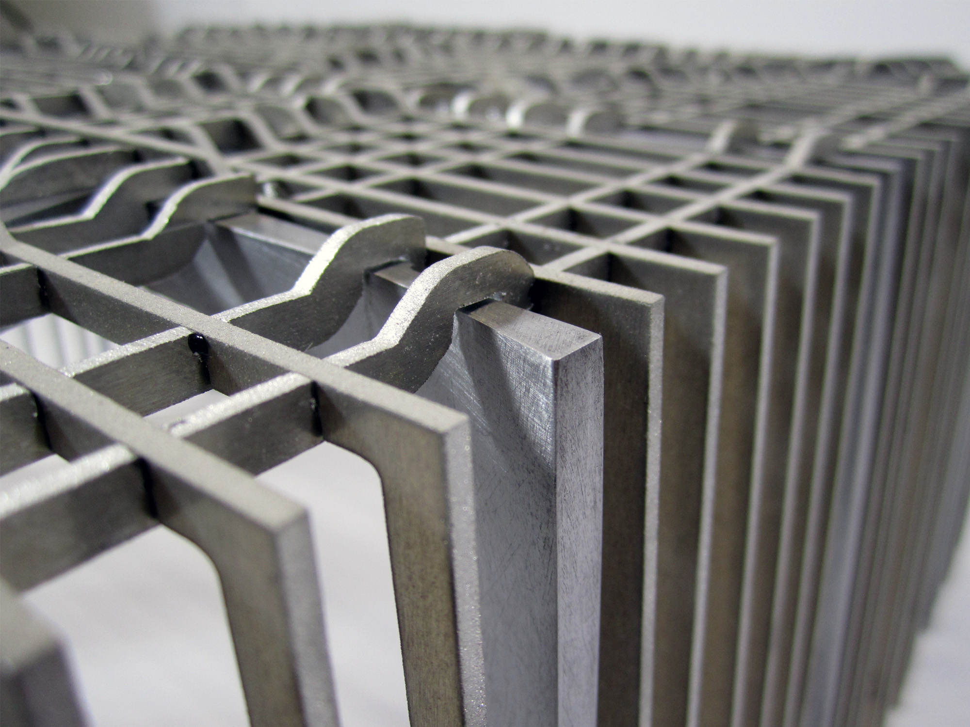
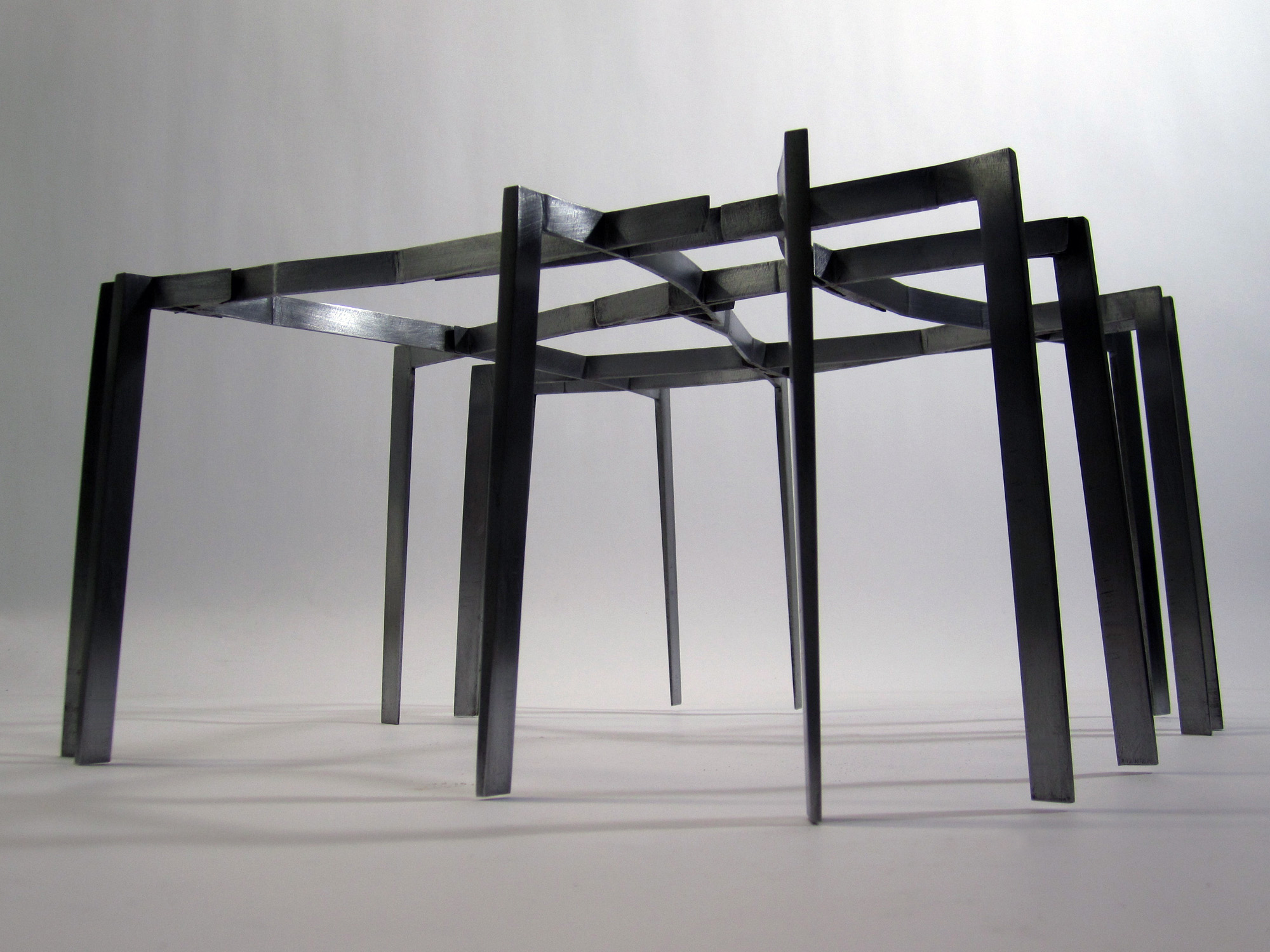
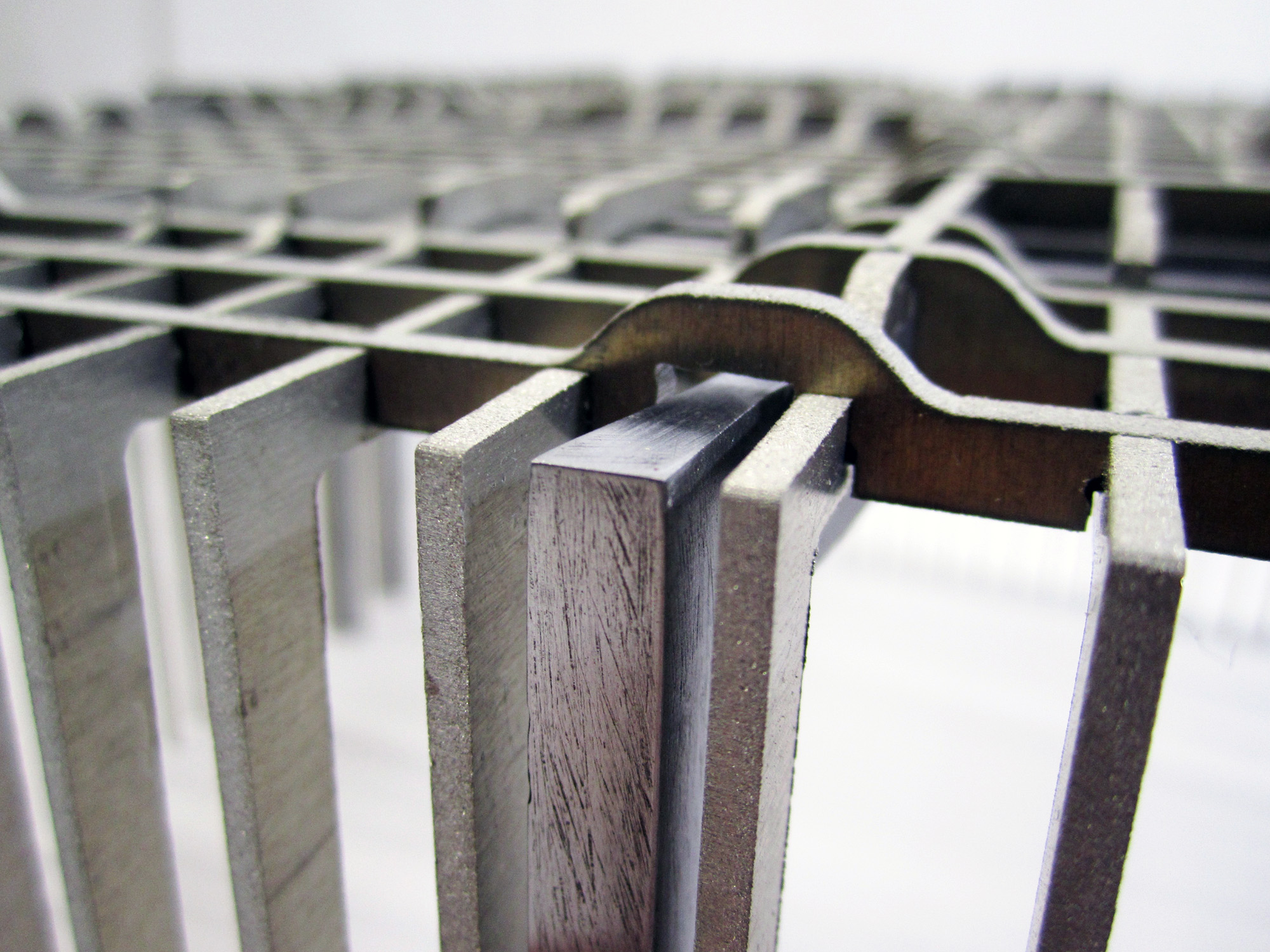
Translation from computational line to material object was based on a decision to assign the manipulated threads the role of primary structure. The remaining grid of the intact non-manipulated threads is expressed as if draped over this frame.
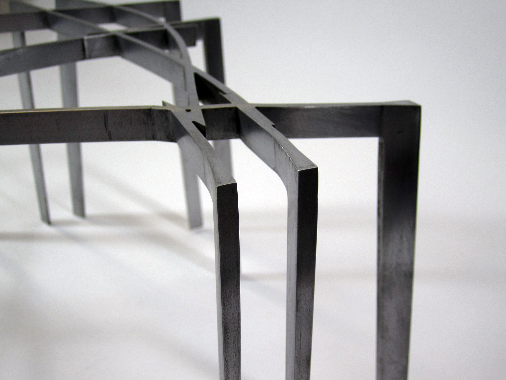
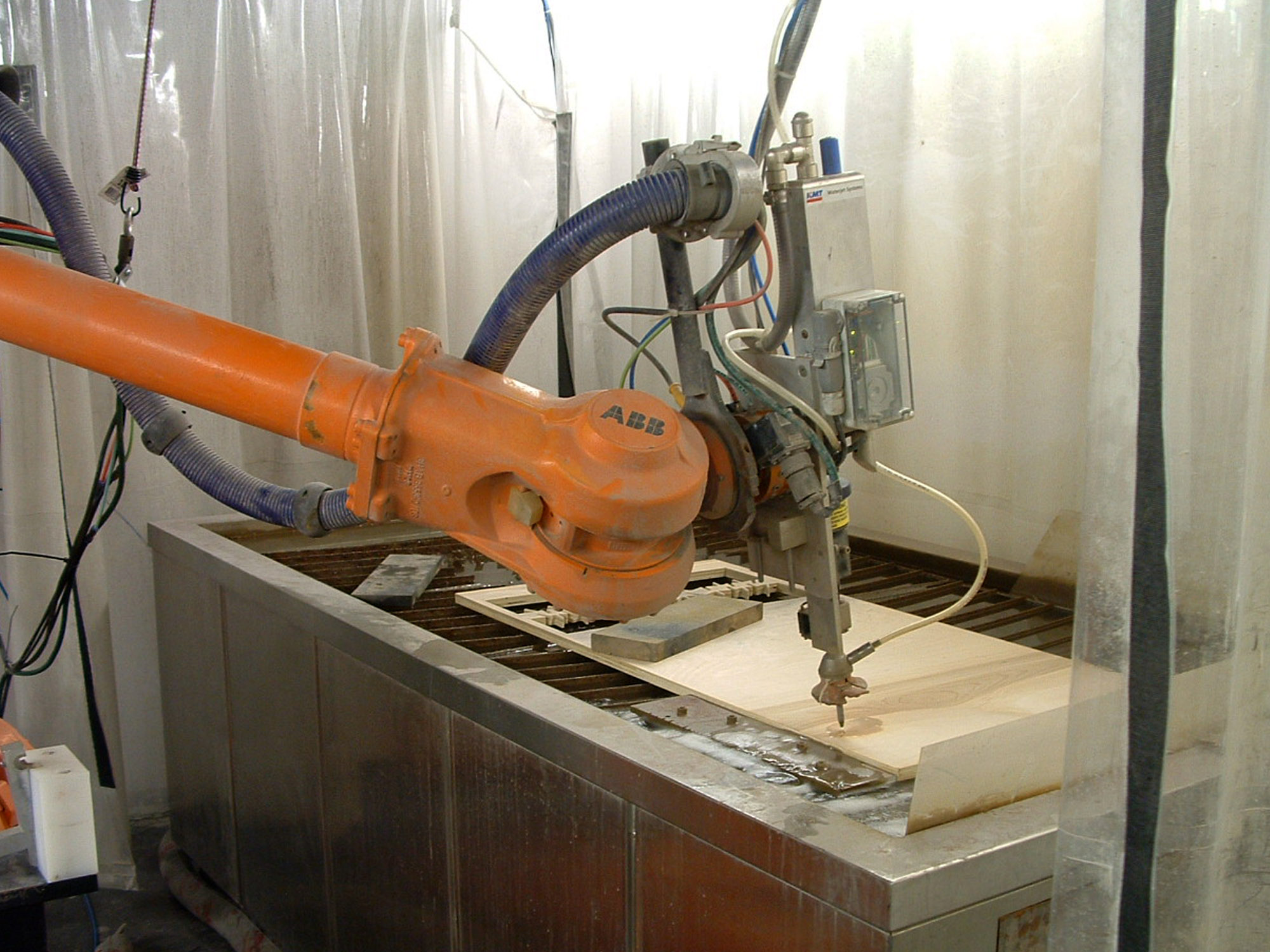
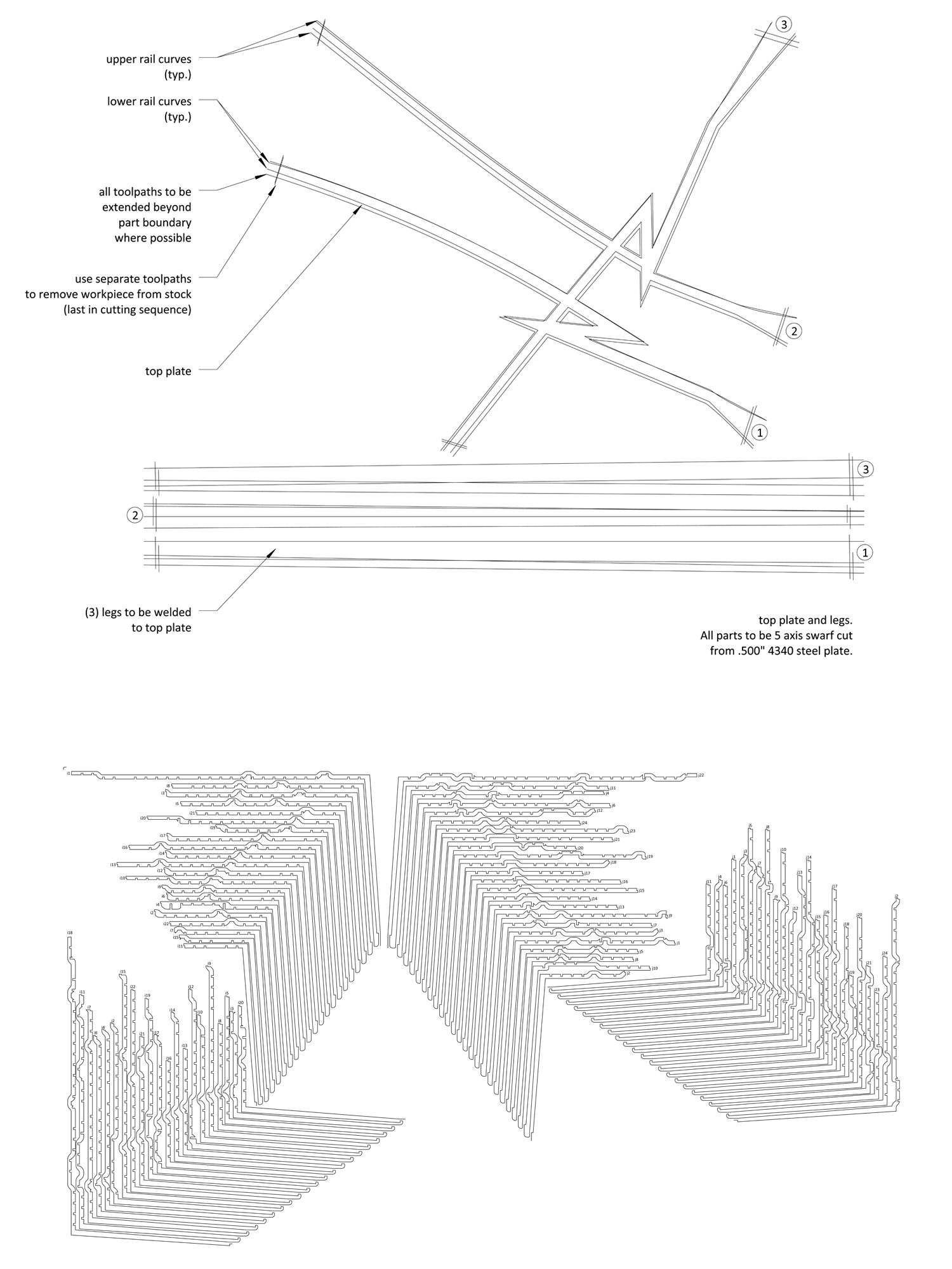
Metal parts were cut with an abrasive waterjet, controlled by a 6 axis industrial robot. The primary frame is cut from steel plate, with the vertical elements cut separately, welded, and ground smooth. The secondary grid is realized in aluminum and assembled with simple notching. The integration of hand-craft techniques required careful strategies to maintain precision alignment during the welding process.
